Matrix is a new set of sensor and driver expansion or break-out boards from FriendlyARM. Matrix has been designed with the FriendlyARM NanoPi Series in mind and most of the Matrix devices will work with a big variety of microprocessors with some GPIO, IIC, and SPI. (I set up the kernel and Debian by the directions on the FriendlyARM Wiki. Beginning at “Make OS Image”. There are some errors and several places that can be confusing. I will duplicate the directions with more detailed notes on another post.)
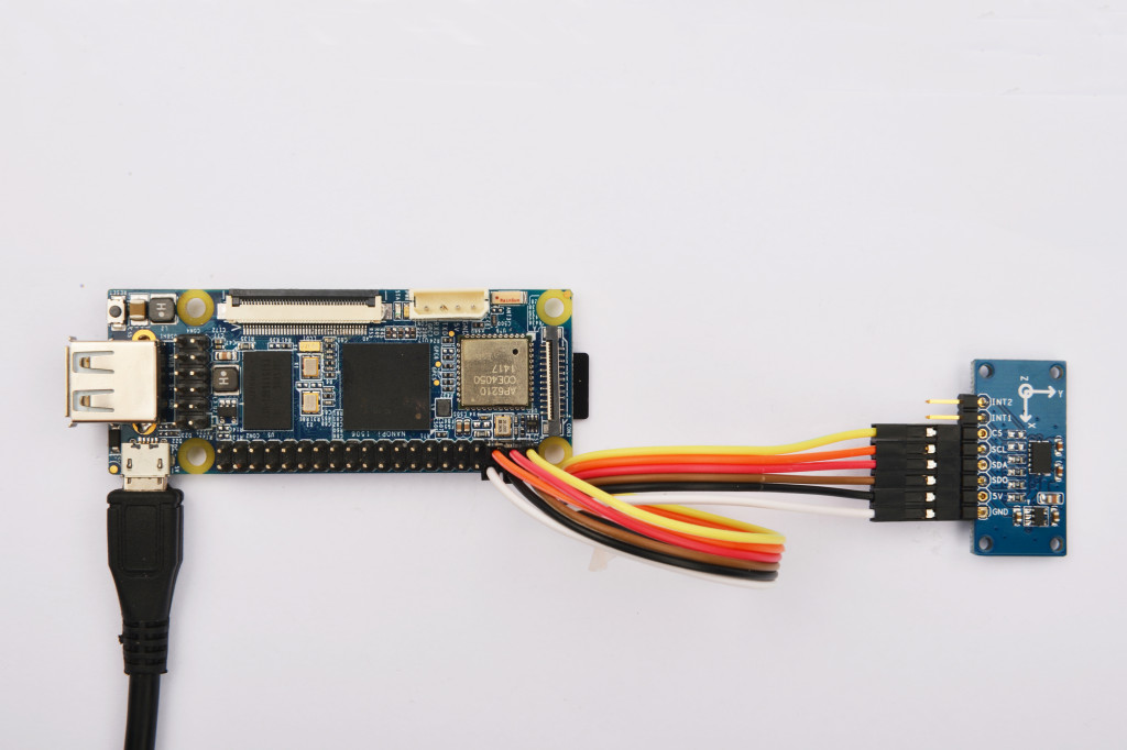
The first device I have tested is the 3 axis accelerometer. This is a board with an Analog Devices ADXL345 which can measure up to plus and minus 16g or 156 meters/s/s. The sample software for Matrix uses the default plus or minus 2g setting. The wiring is simple and uses 8 female-female jumpers. Two of these are interrupts and are not needed for the example code. The Accelerometer Wiki page at FriendlyARM shows adding the Matrix sample library to the NanoPi Debian. (There are some confusing bits and I will add some notes on that on the blog entry about building the kernel and OS).
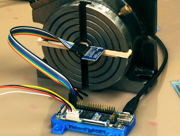
I set up a small machinists rotary indexing table on its side so I could set any angle I liked. The device measures acceleration and the most convenient acceleration around the lab is the Earth’s gravity. Change the angle of the PCB and the values of the X, Y and Z components By shear luck and unrivaled instrumentation skills the PCB of the accelerometer aligned nearly perfectly so that rotation of the indexing table and the chip’s X-axis were co-axial, meaning I could ignore the X-axis output because it would never change. Here is the setup with X perpendicular to the face of the rotary indexer – pointing out of the screen so to speak. Y is to the right, and Z is straight up. These are all relative to the chip, or surface of the PCB. Rotate it 90 degrees to the right clockwise, and Z will point right and Y straight down.
A word about the ADXL345. According to the data sheet, in 2g mode the data is 10 bits in X, Y, and Z, with a 1g reading that varies from 230 to 282 from axis to axis and chip to chip. Any project that uses inertial navigation or measures angles (like a smartphone level app) will need to be calibrated. Does that mean you need an accurate fixture to align each axis with g? No, three arbitrary rotations can be used as long as they meet a simple constraint I’ll describe later. Here is a reading from the above setup. The Z-axis on this chip has a 1g reading of 238.
root@nanopi:~# matrix-3_axis_digital_accelerometer
Get position: (2, 1, 238)
The data sheet gives an RMS noise value of 0.75 LSB (least significant bit) for X and Y and 1.1 LSB for Z. In my fixed rotation test this is around 1 degree noise in X and Y and a little more in Z. Averaging readings will reduce the noise proportional to the square root of the number of readings.
Theory behind this test: I’m assuming that the three nano-scale tuning forks that make up the accelerometers are truly orthogonal – they are independent and measure the components of an acceleration. This means the square root of X squared plus Y squared plus Z squared is the magnitude of any acceleration being experienced by the device.
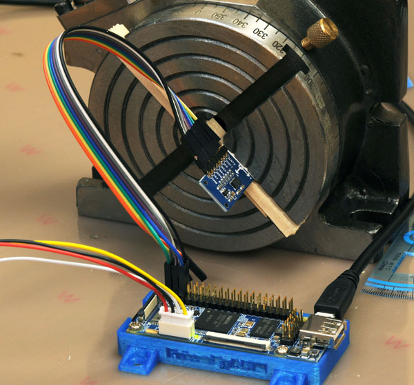
What does this all mean? Since the X axis was aligned well enough to not change and gave a reading close to zero, I can calculate acceleration from square root of Y squared plus Z squared. I can also get the angle of the board from the inverse tangent of Z/Y. I’ll see if I can get a diagram in here. Here is the setup at 45 degrees.
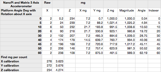
Testing at various angles (and normalizing using the 1g in Z of 238 and the 1g in Y of 272) I compared the indexer angle to the calculated angle. Here mg is milli-g’s and 1g = 1000mg. For calculating the angle of the PCB, only the ratios are used so scaling is not needed. Calibration, yes. Scaling no. Just use the ratio as the vector components of g in order to find the angle form the vertical. Here is an explanation. Imagine the V in that link points straight up and the diagrams are rotated to match.


Recent Comments